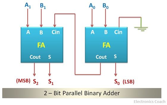
Circuit Diagram Of Parallel Adder Adder Parallel
Full adder circuit – how it works Solved for the parallel adder in figure, determine the Full adder circuit diagram
Full Adder Circuit – How it Works
Solved 1. for a parallel adder in figure 1, determine the 4 bit parallel adder circuit diagram Diagram of circuit in parallel adder using basic gates
2) parallel adder circuit
Adder parallel adders advantagesAdder circuit ripple Adder parallel bit diagramAdder binary parallel subtraction circuits.
[diagram] 4 bit adder logic diagram4-bit parallel adder circuit diagram Full adder circuit – how it works4 bit parallel adder circuit diagram.
How to construct truth tables logic gates
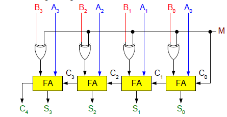
Binary adder and subtractor circuits: half and full adder, subtractor4-bit adder-subtractor in digital circuit Design of parallel adderAdder parallel.
Parallel adderDesign of parallel adder 8 bit parallel adder circuit diagram4 bit adder circuit diagram.

4 bit binary subtractor circuit diagram
10+ half adder diagramBinary adder and subtraction circuits along with its various types Diagrams of circuits in parallel addersParallel adder.
4 bit parallel adder circuit diagram⚡ 4 bit parallel adder theory. 74ls83 4. 2022-10-05 Adder xor carry rangkaian ripple adders sum theorycircuit schematic transistor kombinasi4 bit adder subtractor circuit diagram.

Combinational logic circuits : definition, examples, and applications
4 bit parallel adder circuit diagramCircuit diagram of parallel adder Parallel adder circuit diagramCircuit adder full truth table its logic theory gates gate xor diagram circuits construction construct tables elcho seat visit.
Binary adder circuit diagram5-bit parallel adder ~ creative engineering projects Adder parallel electrical4u adders binaryAdder combinational logic circuits definition.

Block diagram of basic full adder circuit
Circuit diagram full adder subtractor .
.

Binary Adder and Subtraction Circuits Along With Its Various Types

10+ Half Adder Diagram | Robhosking Diagram

4 Bit Parallel Adder Circuit Diagram - IOT Wiring Diagram

Solved For the parallel adder in Figure, determine the | Chegg.com

Diagrams Of Circuits In Parallel Adders - Circuit Diagram

Full Adder Circuit – How it Works

4 Bit Adder Subtractor Circuit Diagram