Circuit Diagram Of Transformer On Load Transformer Equivalen
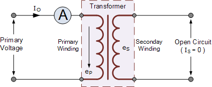
Circuit transformer equivalent diagram primary side secondary referred circuitglobe No load transformer and its phasor diagram Transformer on load condition
Transformer Circuit Diagram - Wiring Diagram
[diagram] electric transformers diagrams Transformer loading and on-load phasor diagrams Circuit of a transformer under load.
Transformer phasor transformers
Electrical topics: circuit diagram of loaded current transformer andTransformer load diagram vector theory operation resistive winding leakage voltage electrical4u reactance current secondary vectorified Transformer load current mmf flux diagram vector different type revolution electrical constantTransformer loading and on-load phasor diagrams.
Transformer circuit diagramTransformer circuit diagram with explanation Phasor diagram ( inductive load) for a single phase transformerTransformer equivalent winding resistance qph quoracdn.

Transformer circuit equivalent phasor secondary primary parameters side referred form determination voltage electrical resistance ratio fig electricalacademia rated
Circuit diagram of transformer on loadTheory of transformer on load and no load operation Electrical transformer schematicDetermination of transformer equivalent circuit parameters.
A simple transformer circuit.Diagram transformer wiring transformers circuit basic primary secondary step voltage coil down simple utexas lectures farside ph teaching edu electric Three phase transformer constructionTransformer vector diagram.

Pin on online electrical & electronics study
Btech first year notes: ideal & practical transformer, basic electricalPractical transformer circuit load basic equivalent diagram its btech year first Equivalent circuit of a transformer? referred to primary and secondaryEquivalent circuit of transformer referred to primary and secondary.
Transformer phasor diagrams calculate methods currentsTransformer current diagram circuit potential loaded electrical typical connected transformers standard Transformer load loading current primary between condition electronics voltage winding tutorials gif ideal phasor difference small through supply wsTransformer construction phase three abb transformers electrical power.

Transformer equivalent elementary
Diagram showing a transformer with load regulationTransformer on load condition Ideal transformer circuit diagramLoad transformer condition diagram circuit phasor figure operation below when.
Transformer phasor knowledge principlesSolved figure 1 shows a transformer connected to a load. 212 Equivalent circuit diagram of single phase transformerDiagram transformer vector phasor load phase single inductive.
06 transformer on load
Transformer as a constant flux device ( transformer on loadTransformer loading and on-load phasor diagrams Ideal transformer in detail with schematics and equationsTransformer ideal equations circuit equivalent phasor derivation losses electricalclassroom.
Transformer working principle how transformer works electrical academiaSolved load figure 1: transformer's circuit diagram • set What is the equivalent circuit of electrical transformer?Transformer secondary circuit equivalent primary side actual referred electrical voltage parameters determination gif winding fig electricalacademia.

Three Phase Transformer COnstruction | Electrical Machines – 1

Pin on Online Electrical & Electronics Study
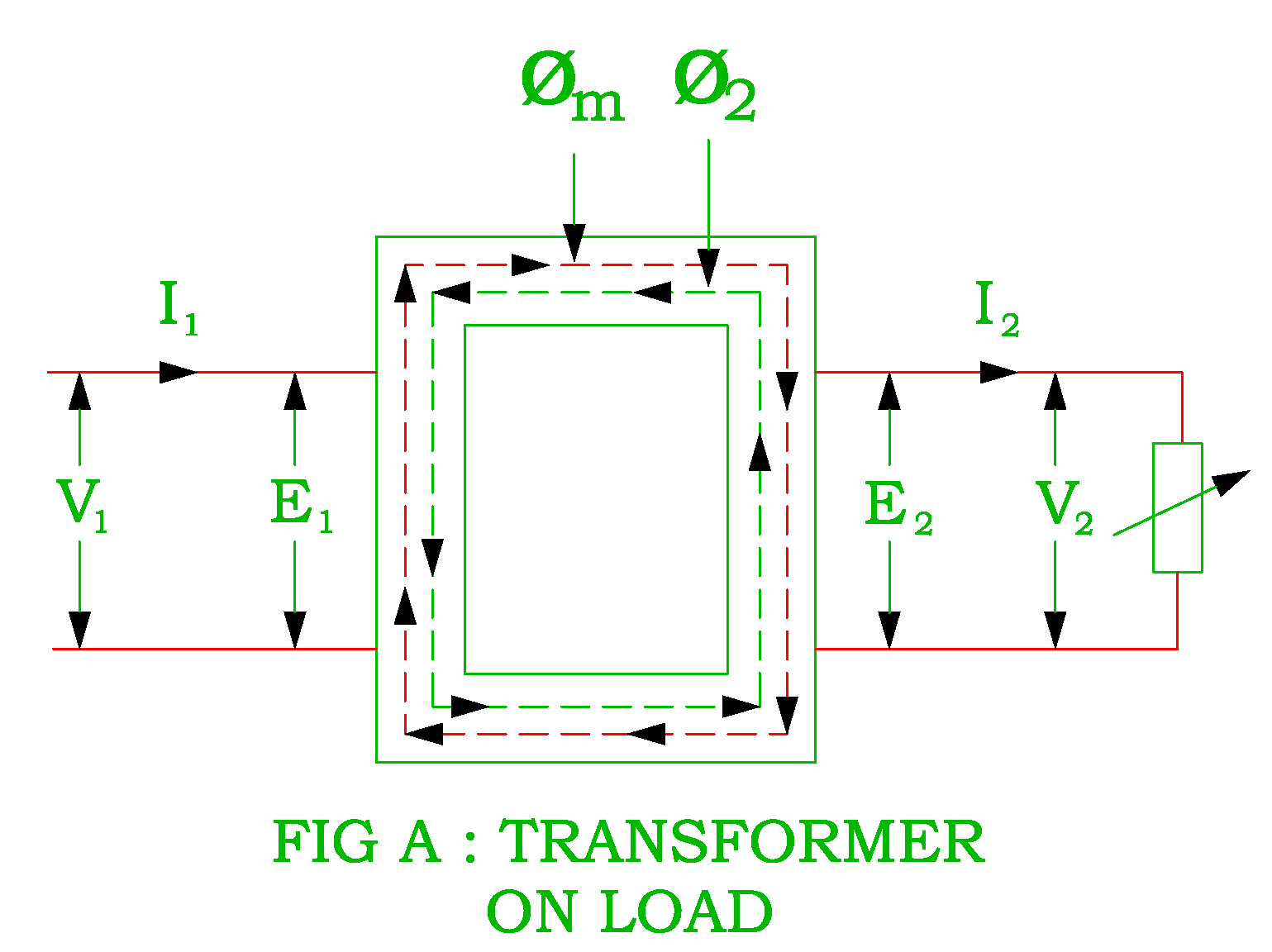
Transformer as a Constant Flux Device ( Transformer on LOAD

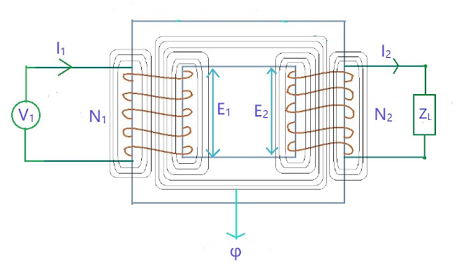
Equivalent Circuit diagram of single phase Transformer

PHASOR DIAGRAM ( INDUCTIVE LOAD) FOR A SINGLE PHASE TRANSFORMER - YouTube

Theory of Transformer on Load and No Load Operation | Electrical4U

Transformer Loading and On-load Phasor Diagrams